If this is your first visit, be sure to
check out the FAQ by clicking the
link above. You may have to register
before you can post: click the register link above to proceed. To start viewing messages,
select the forum that you want to visit from the selection below.
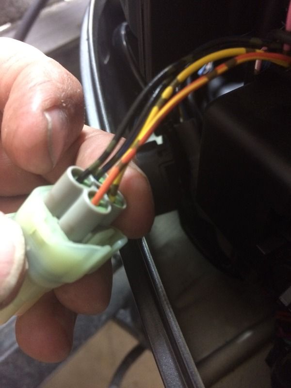
The color coding in the pdf isn't the same as what is on my Suzuki. Just wanting to make sure I hook it all up right. Making my own adapter per the instructions. Here's what I have: (yes, four wires)
Sorry, i dont know. But in the adapter cable you will only need 2 wires connected to the SdS port: power, and data.
If you have a test light you will be able to find which one is the power wire very easily. The other wire for data you should be able to find thru trial and error.
Sorry, i dont know. But in the adapter cable you will only need 2 wires connected to the SdS port: power, and data.
If you have a test light you will be able to find which one is the power wire very easily. The other wire for data you should be able to find thru trial and error.
So....when I find which is data and which is power on the motor end, which color wires do they attach to on the other end? Is one of the wires for the trim gauge?
Black +12V
Black/green? stripe=ground/0V
Orange with stripe = data.
Another picture(unfortunately finnish) is an adapter cable
between engine and nmea adapter.
It is from back( wire side) so it is a mirror of your picture.
Takaa moottoriin = back side to engine
Takaa adapteriin = back side to adapter
Urosliittimet = Connector with male pins
"IF" I were to make the wrong connections, will it damage anything, or will it just not work properly?
Also, the wire designated as 12v+ is purple, not black. Still the +?
Test it with multimeter or tester. Get the 12v + right first. Engine key turned on will enliven it.
In my experience the data wire can then be found safely by trial and error if it comes to that. If the wrong wire is selected, you will simply not get any data. When it is right, you iwll get data.
I would use the multimeter test to confirm power and ground as stated above. However, here are the coded wire meanings, and their functions I pulled from the DF100A, 115A, & 140A service manual.
Y : Yellow - PC Communication line B
O/Y : Orange /Yellow (O wire with a Y stripe) - PC Communication Line A
B : Black - Ground for power
B/Bl : Black /Blue ( B wire with a Bl stripe) - Power source No.2 for ECM
Comment